
2026 Best Motor Braking Resistor for Industrial Use
Choosing the 2026 Best Motor Braking Resistor for Industrial Use starts with the machine, not a generic product ranking. A conveyor stopping under a light load has different braking demands from a centrifuge or hoist. The Motor Braking Resistor converts energy returned by a motor into heat, so its resistance, power rating, and pulse-energy capacity must match the drive and operating cycle. A mismatch may cause overheating, nuisance faults, or longer stopping times.
Details matter. Check the inverter manufacturer’s resistance range, braking current limits, and installation guidance. Then assess how often the motor stops, how long each braking event lasts, and how much time the resistor has to cool. In a control cabinet, restricted airflow and nearby heat sources can change performance. A suitable enclosure, thermal protection, and clearances are not minor extras. They affect dependable operation.
No single model is best for every plant. Compare documented specifications, duty-cycle data, temperature limits, and compatibility with the intended drive. Ask suppliers how published ratings were tested, and verify critical figures against the equipment manuals. A tidy spec sheet can still leave questions unanswered. That is worth noticing.
This guide explains practical selection factors for industrial buyers, including common trade-offs between compact size, cooling, and braking capacity. It also highlights checks that help reduce avoidable failures during installation and service. Use the recommendations as a starting point, not a substitute for engineering review. Real operating conditions can be messy. The right choice is the resistor that meets the application’s verified requirements, with appropriate margin and reliable documentation.
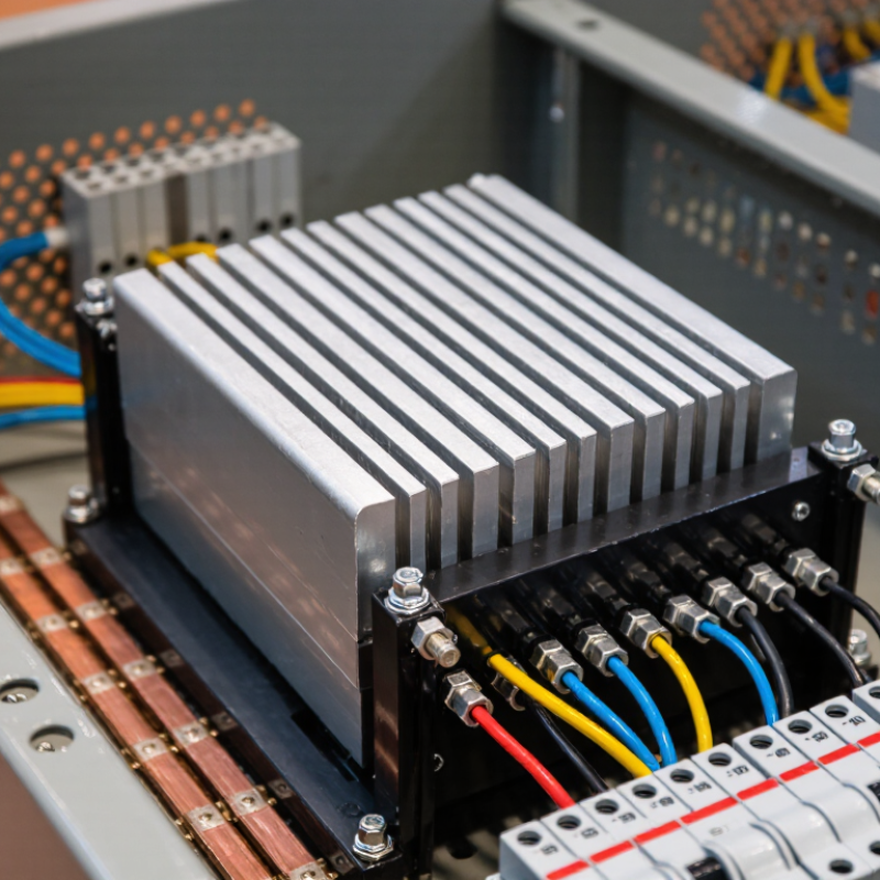
Motor Braking Resistors: Definition and Role in Industrial Drives
2026 Best Motor Braking Resistor for Industrial Use
Motor Braking Resistors: Definition and Role in Industrial Drives
A motor braking resistor converts excess electrical energy into heat during deceleration. In a drive with a braking chopper, energy returned by the motor enters the DC bus. The chopper then directs it to the resistor, helping limit bus voltage and reduce overvoltage trips. The resistor does not create braking torque by itself. It gives the drive a controlled place to dissipate energy.
This role matters in machines that stop often or carry substantial inertia, such as conveyors, centrifuges, and hoists. Picture a loaded conveyor slowing at the end of a cycle: the motor can feed energy back into the drive, and the resistor may become hot within seconds. That heat matters. Resistance, peak power, average duty, and stopping frequency all affect selection. The drive manufacturer’s limits and the machine’s operating profile should guide the calculation.
In practice, a neat calculation can miss real conditions. A resistor sized for occasional stops may overheat during repeated cycles, especially in a cramped cabinet with limited airflow. Check enclosure temperature, ventilation, mounting clearance, and thermal protection. Allow cooling time where possible. The tricky part is that duty cycles change after commissioning, so measured stop times and operating patterns deserve review. A little uncertainty should prompt verification, not guesswork.
2026 Best Motor Braking Resistor for Industrial Use
Motor Braking Resistors: Definition and Role in Industrial Drives
A braking resistor converts electrical energy returned by a drive during deceleration into heat. The chart shows the calculated translational kinetic energy for example loads, using E = ½mv². Actual resistor selection also depends on motor and load inertia, stopping frequency, deceleration time, gravity, and the drive’s braking limits.
How Braking Resistors Control Motor Deceleration
When an industrial motor slows, its inertia can turn the motor into a generator. The drive controls the deceleration ramp, while a braking resistor helps manage the electrical energy returning to the drive. A braking chopper switches this energy into the resistor, where it becomes heat. The resistor does not set the stopping time by itself. The drive’s programmed ramp and the load’s inertia matter too.
On a conveyor, for example, a loaded belt may keep moving after the motor is told to slow. If the returning energy raises the drive’s DC-bus voltage too far, the drive may trip. A correctly selected resistor gives that energy a controlled path. Check resistance, peak braking power, duty cycle, and thermal limits against the drive and application data. The numbers matter. A resistor that handles one short stop may overheat during repeated cycles. Leave room for airflow, keep combustible material away, and follow the equipment manufacturer’s installation instructions. In practice, actual stopping behavior can differ from the calculation, especially when loads vary. That uncertainty deserves a real-world check. Trend drive faults and inspect connections during scheduled maintenance.
Key Specifications for Selecting an Industrial Braking Resistor
For an industrial braking resistor, start with the drive’s specified resistance range. A value below the minimum can cause excessive current and damage the drive’s braking circuit. Check the DC-bus voltage and peak braking current, too. A resistor may tolerate a brief power spike but overheat during repeated stops.
Estimate braking energy from the load’s mass, speed, and stopping frequency. Then compare the required pulse energy and average power with the resistor’s ratings. A conveyor stopping every few seconds needs a different thermal capacity from a machine that stops once per shift. Watch the duty cycle. It matters.
Review the installation conditions as carefully as the electrical figures. Measure the available mounting space, ambient temperature, and airflow around the resistor. A dusty cabinet or blocked vent can reduce cooling in practice. Check the enclosure rating and required clearance against the actual site, not just a clean drawing. Leave room for heat.
A useful selection record includes resistance, peak power, pulse duration, average power, and thermal limits. Confirm each against the drive documentation and the machine’s real stopping pattern. Field measurements can reveal assumptions that were wrong. They are not always convenient, but they help prevent nuisance trips and overheated components.
Comparing Braking Resistor Types for Industrial Applications
Industrial braking resistors convert a motor drive’s excess energy into heat during deceleration. The resistor type affects installation, cooling, and how well the unit handles repeated braking. A choice that works for a lightly loaded conveyor may not suit a crane with frequent stops.
Wire-wound resistors are compact and commonly used for moderate braking loads. Their pulse and duty-cycle limits vary, so check the rated resistance and energy capacity rather than relying on appearance.
Grid resistors allow airflow around their elements and can suit higher-energy applications. They need adequate clearance, and exposed surfaces may collect dust.
Aluminum-housed resistors offer a contained, sturdy format, but their heat dissipation and pulse capacity depend on the specific design.
That matters.
Compare the drive’s braking frequency, stop time, and load inertia with each resistor’s ratings. Then consider ambient temperature, mounting position, and ventilation.
A neat specification sheet can still mislead if it assumes pauses between braking events that your process never has.
Not always obvious.
If the duty cycle is uncertain, measure operating conditions and review the selection with a qualified drive specialist.
How to Choose the Best Motor Braking Resistor in 2026
Choosing the best motor braking resistor in 2026 starts with the drive, not a catalog headline. Check the drive manual for its braking-chopper limits, permitted resistance range, and required resistor power. A resistance below the stated minimum can overload the chopper. A resistor with inadequate pulse capacity may overheat during repeated stops.
Estimate the energy and frequency of each braking event. Motor speed, reflected load inertia, stopping time, and cycles per hour all matter. A conveyor stopping every few seconds needs a different duty rating from a fan that coasts down occasionally. The calculation is a starting point; real operating cycles are often messier than a spreadsheet suggests. Verify the selection against the drive maker’s sizing guidance.
Then consider where the resistor will sit. A cabinet corner with poor airflow can become much hotter than expected. Check ambient temperature, enclosure protection, mounting clearances, and nearby cables or materials. Thermal switches or overload protection can help detect excessive temperature, but they do not replace correct sizing. During commissioning, record stop frequency and resistor temperature under normal production conditions. Small details count. If operating conditions change later, review the sizing again; that step is easy to miss.
| Selection Factor | What to Check | Example or Calculation | Practical Selection Guidance |
|---|---|---|---|
| Drive compatibility | Confirm that the variable-frequency drive has a braking chopper or supports an approved external braking unit. Check its DC-bus operating voltage and resistor connection requirements. | Drive documentation specifies the permissible resistor resistance range and braking-current limit. | Use the drive manufacturer’s limits as the starting point. A resistor alone cannot dissipate regenerated energy unless the drive has a compatible braking circuit. |
| Resistance value | Check the drive’s minimum permitted resistance and maximum braking current. Resistance affects current through the braking circuit. | I = V ÷ R At 750 V and 100 Ω: I = 7.5 A | Do not select a resistance below the drive’s specified minimum. Verify that the calculated current is within the braking chopper’s rating. |
| Peak braking power | Determine the highest voltage across the resistor while the chopper is conducting, then calculate the corresponding instantaneous power. | P = V² ÷ R At 750 V and 100 Ω: P = 5,625 W (5.625 kW) | Check that the resistor assembly can withstand the peak power for the required braking pulse. Peak power is not the same as continuous power. |
| Energy per stop | Estimate the energy that must be removed during each deceleration, including the motor and load’s rotating or moving mass. | E = ½J(ω₁² − ω₂²) For translation: E = ½m(v₁² − v₂²) | Account for load inertia, speed change, gravity-driven loads, and losses. Use the drive or machine manufacturer’s method where available. |
| Average thermal load | Consider the energy dissipated over a complete operating cycle, not only the power during one braking pulse. | Pavg = Ecycle ÷ Tcycle 20 kJ dissipated every 10 s = 2 kW average | Compare the calculated average load with the resistor’s rated power under the actual ambient temperature, mounting, enclosure, and airflow conditions. |
| Braking frequency and duty | Record braking-event duration, events per hour, cycle time, and any continuous or repeated braking periods. | Example duty ratio: 2 s braking in a 10 s cycle = 20% duty. | Use the resistor manufacturer’s pulse-energy and duty-cycle ratings. A short pulse rating does not establish suitability for frequent or continuous braking. |
| Resistor construction | Compare available construction types, enclosure, protection rating, and resistance stability for the installation environment. | Wire-wound and metal-grid designs are commonly used in industrial braking applications; ratings depend on the specific assembly. | Choose a construction with documented pulse and thermal ratings. Select enclosure and ingress protection to suit dust, moisture, vibration, and installation location. |
| Temperature and installation | Check maximum surface temperature, clearance, ventilation, ambient temperature, and nearby combustible materials. | Resistors can become very hot during braking; required clearances and mounting orientation are product-specific. | Follow the resistor and drive installation instructions. Provide suitable guarding and thermal protection where required by the application and local codes. |
| Protection and monitoring | Review overtemperature protection, thermal switches, braking-circuit fault monitoring, and protective-device coordination. | A thermal switch can provide an interlock or alarm if the resistor assembly exceeds its specified temperature. | Include appropriate protection in the machine design. Do not rely on the resistor’s power rating alone to protect against a fault or overload. |
| Final verification | Validate resistance, peak current, pulse energy, average power, ambient derating, and drive compatibility together. | For each cycle, compare braking energy with the resistor’s documented pulse-energy capacity and thermal recovery limits. | Obtain final ratings from the drive and resistor documentation. Have a qualified engineer verify the design before commissioning. |
| Note: The numerical calculation examples are illustrative, not universal product ratings. Actual braking voltage, permissible resistance, current limits, pulse capacity, and continuous power depend on the drive, resistor assembly, load, and operating cycle. | |||
